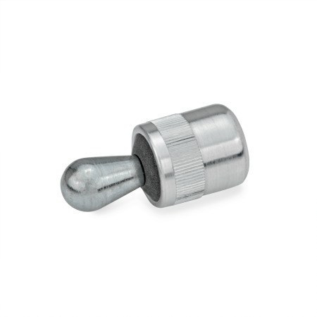
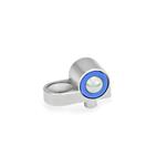
SA | Thrust pin steel, without seal |
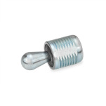
KA | Thrust pin plastic, without seal |
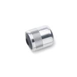
SB | Thrust pin steel, with seal |
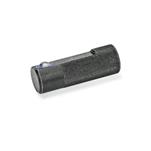
KB | Thrust pin plastic, with seal |
d1 | Side thrust F0 in N Type SA / SB | Type KA / KB | a1 | a2 | d2 | d3 H8 | h | ||
---|---|---|---|---|---|---|---|---|---|
3 | 10 | 20 | 40 | 10 | 1,5 | 3,5 | 6 | 6 | 7 |
5 | 20 | 50 | 100 | 20 | 2,5 | 5,7 | 10 | 10 | 12 |
6 | 40 | 75 | 100 | 40 | 3 | 7,7 | 10 | 10 | 12 |
8 | 50 | 100 | 150 | 50 | 4 | 8,9 | 12 | 12 | 14 |
10 | 100 | 150 | 205 | 100 | 5 | 10,7 | 16 | 16 | 18 |
d1 | l1 -1 | l2 ±0,5 | l3 -2 | l4 | w | x1 | x2 | Code no. for mounting tool |
---|---|---|---|---|---|---|---|---|
3 | 7 | 4 | 7 | 4 | 1 | 1 | 0,75 | GN 715.1-3 |
5 | 11 | 6,7 | 11,5 | 6 | 1,6 | 1,7 | 1,3 | GN 715.1-5.6 |
6 | 11 | 10,7 | 11,5 | 10 | 2 | 1,9 | 1,4 | GN 715.1-5.6 |
8 | 13 | 13,9 | 14 | 13 | 2,6 | 2,7 | 2,1 | GN 715.1-8 |
10 | 17 | 16,7 | 18 | 16 | 3,2 | 3,4 | 2,7 | GN 715.1-10 |
w = Movement of pin For contact points (workpiece height) between a1 and a2 a value for x has to be used lying between x1 and x2 (interpolation). |
|||||||||||
By observing the above values the full movement of the side thrust pin will be available to cover the tolerance of the workpiece. |
|||||||||||
For inserting the side thrust pins the use of a mounting tool Mounting Tools GN 715.1 is recommended. |
|||||||||||
Eccentric Bushings GN 715.2 are a tooling accessory for GN 715. They enable a precise optimum setting of side thrust pins. This allows an adjustment to l0 to accommodate for instance a larger tolerance range on a workpiece. |
Our service team is available from Monday to Friday between 7:00 AM and 5:30 PM: +49 7723 6507 - 0