Functioning principle and applications of worm gear reducers
Functioning principle of gear reducers
Worm gear reducers consist of a worm shaft and a worm wheel. The worm shaft has a screw-shaped structure, while the worm wheel has a gear-like shape with inclined teeth. This design allows for low-friction and quiet torque transmission. The screw-shaped movement of the worm shaft produces a large gear ratio, which can convert lower speeds into higher torques.
Applications of worm gear reducers
Worm gear reducers are used in a variety of applications, including:
- Worm gear reducers are frequently used in industrial systems to drive machines such as conveyor belts, mixing machines, packaging machines and lifting mechanisms
- In addition, worm gear reducers can provide clever solutions for automatic transmissions and steering systems in vehicle manufacturing as well as transportation
Advantages and disadvantages of worm gear reducers
Advantages of worm gear reducers
Worm gear reducers have a number of advantages over other types of gear boxes. Here are some of them:
- High efficiency: Worm gear reducers offer excellent efficiency because they have a high gear ratio with low energy loss. This enables the use of worm gear reducers in applications requiring precise torque transmission with low energy consumption.
- Large gear ratios: Worm gear reducers offer the ability to achieve high gear ratios within a compact space. This means that a low input rotation speed can be converted into a higher output rotation speed. This ability makes worm gear reducers ideal for applications that require fine speed regulation.
- Self-locking and reliable torque transmission: Worm gear reducers are self-locking, meaning that they can hold the load without the need for an additional brake mechanism. This makes them ideal for applications where safety and reliability are important. Depending on the gear ratio, worm gear reducers from Ganter are self-locking.
- Compact and space-saving: The design of worm gear reducers makes them very compact, requiring little space.
- Low-noise: Worm gear reducers generally operate with very low noise and produce few to no vibrations during operation.
- Simple installation: Worm gear reducers are generally simple to install. All worm gear reducers from Ganter are encapsulated in an aluminum housing and protected from dust ingress, making them maintenance-free since they are permanently lubricated with grease. This makes them ideal for maintenance-free applications that require quick and easy installation.
Disadvantages of worm gear reducers
- Axial load: Due to the screw shape of the worm wheel, worm gear reducers produce considerable axial load. This load can result in additional stress on the shafts and bearings and frequently requires special bearing and housing structures to absorb these forces.
- Limited speed: Worm gear reducers are usually designed for lower speeds. High speeds can lead to a phenomenon called “self-locking”, in which the worm wheel blocks itself and the gear box is no longer able to transmit torque. This limits the maximum speed of the gear box.
- Precision and backlash: Due to the production process and the geometry of the worm wheels, worm gear reducers can exhibit a certain degree of backlash. This backlash can cause undesirable vibrations and imprecision in applications that require high precision.
Despite these disadvantages, worm gear reducers are used in many applications due to their high gear ratios, compact design and the ability to transmit high torques, including in areas like industrial automation, lifting machines, conveyor systems and drives for heavy load applications.
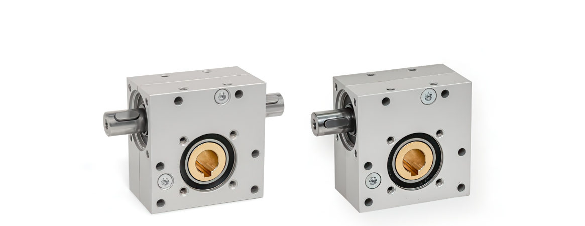
Structure of worm gear reducers
The typical worm gear reducer from Ganter consists of the following components:
- Encapsulated housing of aluminum, anodized
- Worm of steel
- Worm wheel of brass
- Ball bearing of steel, sealed
Application examples
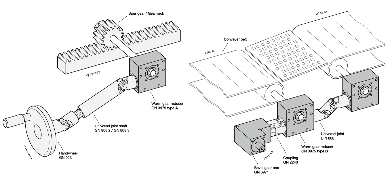
- Bevel gear boxes GN 3971
- Worm gear reducers GN 3975
- Spur gears GN 7802
- Gear racks GN 7822
- Universal joint shafts GN 808.2
- Universal joint shafts GN 808.3
- Disk handwheels GN 923
- Couplings GN 2240