GN 148.4 Vibration Damping Elements Rubber, Flange Steel, for Tensile / Compressive Load

Vibration Damping Elements GN 148.4: Rubber, Flange Steel, for Tensile / Compressive Load
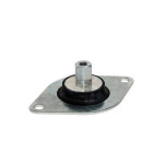
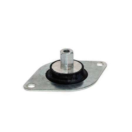
Type: A - For compressive load
Material: ST - Steel

Product description

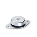
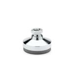
Vibration damping elements GN 148.4 absorb vibrations to protect the environment of a machine from vibrations and noise.

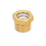
Type B is designed primarily for tensile loads, making it suitable for overhead applications. In combination with type A, it can also be mounted on the side (see application example).

Specification

Vibration damping element
Natural rubber (NR)

  • Vulcanized
  • Black
  • Operating temperature -40 °C to +80 °C
  • Hardness Shore A ±5
    • Soft40
    • Medium60
    • Hard70

Contact plate / Threaded insert
SteelST


RoHS

Hide technical drawing
GN 148.4 Vibration Damping Elements, Rubber, Flange Steel, for Tensile / Compressive Load sketch

Article options / Table

Type

AFor compressive load
BFor tensile / compressive load
Show / Hide columns
d1
Type A

Type B
d2bd3
Type B
d4h1h2Length lmA/F
40-M 875-9332,51149615
-56M 875679332,51149615

Build & Price

Diameter d1 (type A)
Diameter d1 (type B)
d2
Type


Hardness


Material

Diameter d1 (type A)
Diameter d1 (type B)
d2
Type


Hardness


Material

Load Capacity

7d06df36-7ae6-44d5-ae76-a3b047074a2a

Terms

F1 = Static compressive load
F2 = Static tensile load
F3 = Static compressive load
s1 = Compression (spring travel) under load F1
s2 = Elongation (spring travel) under load F2
s3 = Compression (spring travel) under load F3
The spring rate R is the load which causes the damping element to be compressed / elongated by 1 mm.

Formula for calculating spring rate: R = F/s

The values listed in the table can be used to determine the degree of isolation as a function of the interference frequency, in accordance with the approach shown on page XYZ.
The information on load capacity represents non-binding guidelines and excludes any liability. They generally do not constitute a guarantee of quality. Whether a product is suitable for a particular application must be determined in each individual case by the user.

Show / Hide columns
d1
Type A
Hardness
in Shore
Max. static load F1
in N
Spring rate R1
in N/mm
Max. compression s1
in mm
40406543272
40609904952
40701543771,52
Show / Hide columns
d1
Type B
Hardness
in Shore
Max. static load F2
in N
Spring rate R2
in N/mm
Max. elongation s2
in mm
Max. static load F3
in N
Spring rate R3
in N/mm
Max. compression s3
in mm
5640863431,528817,65
56601000500215130,25
56701806903220140,25

Application Example

5a6da1d2-7dff-4ff7-a109-4b2717123b50

Guide to Selecting Vibration Damping Elements

For correct selection of a standard part used for vibration damping, it is first necessary to understand the terms listed below:

The disturbing frequency is the frequency emitted by the machine, e.g. the number of strokes per minute, measured in Hertz, or the main shaft rotation speed, measured in revolutions per minute.

The static load in Newtons is the load that acts on a single vibration damping element. The total weight of a machine is divided by the number of damping elements. In an optimal arrangement, each element bears the same load.

The degree of isolation, given in percent, is the measure of the absorption of the disturbing frequency, i.e. the damping.

The compression or the spring travel is the maximum change in the height of the damping element in mm.

The calculated spring rate in Newtons/millimeter is the load that causes a height change of 1 mm.

45349c40-50cb-4b57-a1e2-265684d431cd

Example with the following assumptions: Disturbing frequency = 50 Hz; load = 120 N; desired degree of isolation = 90 %

The selection of a suitable vibration damping element begins with determining the required compression. This can be taken from the y-axis of the diagram at the intersection of a vertical line at 50 Hz (x-axis) and the
characteristic curve of the desired degree of isolation of 90 %. The example values yield a compression of 1 mm.
With the compression determined in this way and the given static load, it is possible to calculate the required spring rate with the following formula:

Static load F [N] per damping element / Spring travel s [mm] = Spring rate [N/mm] => 120 N / 1mm = 120 N/mm

Based on the calculated spring rate and the desired shape, the appropriate damping element can then be selected. The respective spring rates are given in a table on the corresponding standard sheets. In making the selection, it is important to ensure that the spring rate at least satisfies the calculated value.
The example arrives at a vibration damping element with article number 148.3-46-M10-A-60-S and a spring rate of 138.3 N/mm.

Selected Part (How to order)

Total (net)
21,75
plus VAT 4,13 €
gross 25,88 €
In stock
Weight: 0,147 kg
If this article is new in our product range, it may happen that details concerning weight are as yet not listed.
If you do need weight details, please contact our Sales Department!
Phone +49 7723 6507 - 0
RoHS: Yes
This article is RoHS-compliant in application of Annex III., which means it complies with EU Directive 2011/65/EU, including extension (2015/863/EU), for restricting the use of certain hazardous substances in electrical and electronic devices. The Directive regulates the use of hazardous substances in devices and components. The implementation in national law is summarily described with RoHS(Restriction of (the use of certain) hazardous substances).
Customs tariff number
40169991
Please note our order discounts.
With a total value (net) per order:
from 175,00 € -> 10 % discount
from 275,00 € -> 20 % discount
from 375,00 € -> 30 % discount

Surcharge for small volume purchases:
-> 15,00 Euro
for value of goods less than 25,00 €
-> 10,00 Euro
for value of goods from 25,00 to 49,99 €
Save as favourite
Recommend a product

CAD data

CAD Download Tutorial

Do you find your product ?

Our service team is available from Monday to Friday between 7:30 AM and 5:00 PM: +49 7723 6507 - 0

To the customised elements | To the contact persons

GN 148.4-40-M8-A-40-STGN 148.4-40-M8-A-60-STGN 148.4-40-M8-A-70-STGN 148.4-56-M8-B-40-STGN 148.4-56-M8-B-60-STGN 148.4-56-M8-B-70-ST

Your contact

You are looking for a Ganter partner near you?

Ganter-Service

Our service team is available from Monday to Friday between 7:30 AM and 5:00 PM:

Request Callback