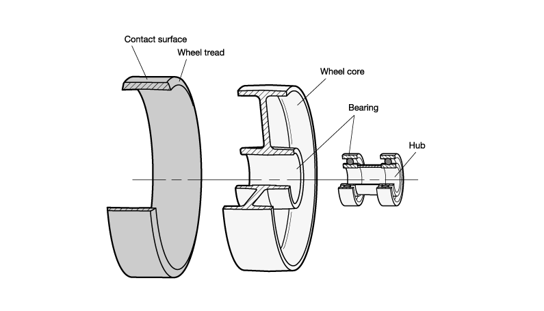
Wheel Structure
A wheel consists of the components contact surface, wheel tread, wheel core, bearing and hub. The properties and functions of these components are explained below.
- The contact surface is the part of the wheel that touches the floor. It is also referred to as the profile. The contact surface may be smooth or textured to increase traction.
- The wheel tread is the tire of the wheel. Its outer surface forms the contact surface. It can be made of various
materials, and the associated material properties determine the potential areas of application for the wheel. It can be glued, vulcanized, cast or injection molded and is always firmly connected to the wheel body. - The wheel core is the main structural component of the wheel and serves as the rim, forming the connection between the tread and the bearing. Various designs are possible, such as versions with or without spokes, as well as a variety of materials. It can consist of a single part or multiple connected parts.
- The bearing and the hub form the interface between the fixed axle and the wheel, which rotates around the axle. The selected bearing type has a direct influence on the running properties. A variety of wheel bearing types are used, such as ball bearings, roller bearings or friction bearings that run directly in the hub bore.
Wheel Tread, Materials
The following material options are available for the wheels: Rubber, polyurethane, polyamide and phenolic resin. These materials are explained below.
The rubber tread is made of natural rubber and/or synthetic rubber-based elastomer. It is applied to the wheel either via vulcanization or injection molding and has the following properties.
+ High elasticity and ease of movement
+ Gentle on floors
+ Low-noise
+ Vibration-damping
- High starting and rolling resistance
- Abrasion possible on rough floors
The polyurethane tread consists of an elastomer produced exclusively from synthetic materials. The polyurethane is applied to the wheel either by casting or injection molding and has the following properties.
+ Low starting and rolling resistance
+ High elasticity
+ Good resistance to wear and tear
+ Gentle on floors
+ Leaves no marks
+ Resistant to many aggressive media
On single-part wheels, the tread is determined by the base material of the wheel body; in other words, the tread and wheel core are produced from the same material in a single manufacturing process. The characteristic properties of the respective materials are explained below.
Polyamide:
+ Good resistance to wear and tear
+ Low starting and rolling resistance
+ Leaves no marks
+ Resistant to many aggressive media
- Can absorb and release moisture
Phenolic resin:
+ Heat resistant
+ Resistant to many aggressive media
- Lower wear and tearing resistance
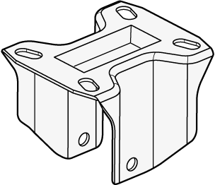
Bracket Structure
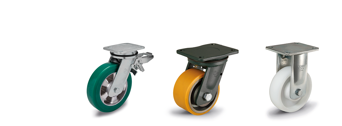
When a wheel is combined with a bracket, this is referred to as a swivel caster or rigid caster, depending on the bracket type. The bracket is the connecting element between the wheel and the cart. The various types are swivel brackets, swivel brackets with total lock brakes and rigid brackets.
Swivel Bracket
The sviwel bracket rotates around its vertical axis when the pushing direction changes. The wheel axle is offset from the bracket axis to provide for good maneuverability of the cart. Maneuverability refers to both the ability to steer the cart and to move in a straight line.
Swivel brackets are made up of the individual components of mounting plate, wheel support fork, bearing, ball race ring, stud (or center hole) and, depending on the design, a dust seal.
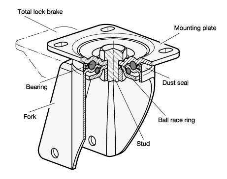
The wheel support fork holds the wheel via the wheel hub and is connected to the fitting plate by the bearing.
The bearing consists of a double axial ball bearing and allows the wheel support fork to rotate beneath the fitting plate. It is lubricated with grease and the dust seal protects it from dirt. The bearing is held together by the stud and the ball race ring, which forms the bottom surface.
The bracket is affixed to the cart via the fitting plate. The slotted holes make it easy to mount multiple casters in parallel.
A swivel bracket equipped with a total lock brake can be locked to prevent turning of both the wheel and the bracket.
Rigid Bracket
The rigid bracket consists of die-cut sheet steel and holds the wheel via the wheel hub. This combination is also called a rigid caster and helps keep the cart moving in a straight line.
Operating Conditions
The type of the floor and the possible obstacles are factors that influence the amount of force required to move the cart as well as the transmission of vibrations and the wear on the wheel.
Based on the characteristics of the floor, the guidelines apply to selecting the right wheel:
• For irregular floors and in the case of obstacles, the wheels should have soft and thick tread and large diameter.
• For smooth floors and heavy loads, the wheels should have hard tread.
The table below provides a simple breakdown of the suitable tread for every floor type.
| Flooring | Suitable tread material |
| Tiles | Plastic material, polyurethane or rubber |
| Asphalt | Rubber |
| Synthetic resin, concrete | Plastic material, polyurethane or rubber |
| Unpaved | Rubber |
| Grating | Rubber |
| With chips | Rubber |
The table summarizes a number of general resistances for each wheel series to make the selection process easier.
Given the numerous chemicals, solvents, etc., precise information cannot be offered since materials with low resistance to a general class of substances may have high resistance to particular substances and vice versa. The concentration, temperature and length of exposure also has a major influence. Users should perform their own resistance tests with relevant materials.
| Resistant to: | GN 22868 | GN 22870 | GN 22872 | GN 22873 | GN 22874 | GN 22875 | GN 22880 |
| Alcohol | + | o | + | o | o | + | + |
| Hydrocarbons | + | o | + | o | o | o | + |
| Solvents | - | - | o | - | - | - | o |
| Weak acids | + | + | + | + | o | + | + |
| Strong acids | - | - | o | - | - | - | o |
| Weak alkali | o | o | + | o | o | o | + |
| Strong alkali | - | o | o | o | o | o | o |
| Water | o | + | + | + | + | o | + |
| Resistant to: | GN 22882 | GN 22884 | GN 22885 | GN 22886 | GN 22887 | GN 22892 | GN 22894 |
| Alcohol | + | + | + | + | + | + | + |
| Hydrocarbons | + | + | + | + | + | + | + |
| Solvents | - | - | - | - | - | o | + |
| Weak acids | + | + | o | o | o | o | + |
| Strong acids | - | - | - | - | - | - | - |
| Weak alkali | o | o | o | o | o | + | + |
| Strong alkali | o | o | - | - | - | o | - |
| Water | + | + | o | o | o | + | + |
+ Resistant, o Limited resistance, – Not resistant
Depending on the ambient temperature, the load capacity must be adjusted based on the temperature correction factors given in the table.
| Ambient temperature | |||||||
| from | to | GN 22868 | GN 22872 | GN 22873 | GN 22874 | GN 22875 | GN 22882 |
| -40 °C | -20 °C | - | - | - | 0,4 | 0,4 | - |
| -20 °C | 0 °C | 1 | 0,8 | 0,8 | 1 | 1 | 1 |
| 0 °C | +20 °C | 1 | 1 | 1 | 1 | 1 | 1 |
| +20 °C | +40 °C | 1 | 1 | 1 | 1 | 1 | 1 |
| +40 °C | +60 °C | 0,9 | 0,85 | 0,85 | 0,85 | 0,85 | 0,9 |
| +60 °C | +80 °C | 0,8 | 0,5 | 0,5 | 0,6 | 0,6 | 0,7 |
| +80 °C | +120 °C | - | - | - | - | 0,4 | 0,4 |
| > +120 °C | - | - | - | - | - | - |
| Ambient temperature | |||||||
| from | to | GN 22884 | GN 22885 | GN 22886 | GN 22887 | GN 22892 | GN 22894 |
| -40 °C | -20 °C | - | - | - | - | 0,5 | 0,5 |
| -20 °C | 0 °C | 1 | 1 | 1 | 1 | 1 | 1 |
| 0 °C | +20 °C | 1 | 1 | 1 | 1 | 1 | 1 |
| +20 °C | +40 °C | 1 | 1 | 1 | 1 | 1 | 1 |
| +40 °C | +60 °C | 0,85 | 0,9 | 0,9 | 0,9 | 0,9 | 1 |
| +60 °C | +80 °C | 0,6 | 0,8 | 0,8 | 0,8 | 0,7 | 1 |
| +80 °C | +120 °C | - | - | - | - | 0,6 | 1 |
| > +120 °C | - | - | - | - | - | 1 |
1 = 100% of the load capacity specified in the standard sheet
The load capacities given for industrial casters in the standard sheet refer to a speed no greater than 4 km/h. At higher speeds, the load capacity must be adjusted based on the speed correction factors given in the table.
| Speed | |||||||
| from | to | GN 22868 | GN 22872 | GN 22873 | GN 22874 | GN 22875 | GN 22882 |
| 0 km/h | 4 km/h | 1 | 1 | 1 | 1 | 1 | 1 |
| 4 km/h | 6 km/h | 0,7 | - | - | - | 0,8 | 0,6 |
| 6 km/h | 10 km/h | 0,5 | - | - | - | - | - |
| 10 km/h | 12 km/h | 0,4 | - | - | - | - | - |
| 12 km/h | 16 km/h | 0,3 | - | - | - | - | - |
| Speed | |||||||
| from | to | GN 22884 | GN 22885 | GN 22886 | GN 22887 | GN 22892 | GN 22894 |
| 0 km/h | 4 km/h | 1 | 1 | 1 | 1 | 1 | 1 |
| 4 km/h | 6 km/h | 0,6 | 0,8 | 1 | 0,8 | - | - |
| 6 km/h | 10 km/h | - | - | 0,8 | 0,6 | - | - |
| 10 km/h | 12 km/h | - | - | 0,7 | 0,5 | - | - |
| 12 km/h | 16 km/h | - | - | 0,6 | 0,4 | - | - |
1 = 100% of the load capacity specified in the standard sheet
The speed correction factors should only be regarded as general guide values, as many application-specific factors can affect the load capacity. A corresponding check should be carried out by the user.
Technical Instructions
Maneuverability is the ability of a cart to be moved more or less easily during use. Production halls with limited space or winding paths require good maneuverability to make the operator‘s work easier.
In general, swivel brackets allow for easy direction changes, while rigid brackets ensure good directional stability. Rigid brackets must be mounted parallel to each another to avoid distorsion.
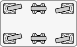
The table shows the most frequently used arrangements and their features.
| Diagram | Caster arrangement | Special features | Application examples |
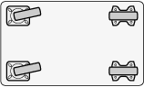 | 2 swivel casters, 2 rigid casters, identical height | + Most common arrangement + Good directional stability + Good cornering - Poor maneuverability in tight spaces | Workshops, warehouses |
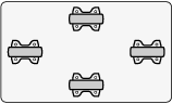
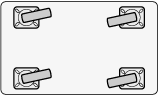 | 4 swivel casters, identical height | + Good steering ability + Can be turned on the spot + Good maneuverability in tight spaces - Poor straight travel | Supermarkets, industrial plants, logistics centers |
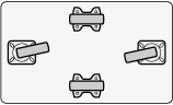
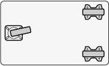 | 1 swivel caster, 2 rigid casters, identical height | + Inexpensive + Good steering ability + Can be turned on the spot + Good maneuverability in tight spaces - Poor directional stability - Tends to tip over | Small carts, light loads |
 | 4 swivel casters, 2 rigid casters, identical height | + Good for heavy loads + Good load distribution for long equipment + Good steering ability + Can be turned on the spot - High cost | Parcel distribution, postal service, train stations, heavy loads, long equipment |
 | 4 rigid casters, the middle rigid casters have a higher overall height | + Inexpensive + Good directional stability + Good steering ability - Tends to tip over | Assembly lines, industrial carts |
 | 2 swivel casters, 2 rigid casters, the rigid casters have a higher overall heigh | + Good directional stability + Can be turned on the spot - Tends to tip over | Workshops, warehouses, long material carts |
The static load capacity is the maximum load that can be supported by a stationary wheel or caster without causing permanent deformation that impairs its functionality. A wheel mounted on a device that is rarely moved and therefore almost always remains in the same position is defined as statically loaded.
The dynamic load capacity of a wheel or caster is the maximum load that it can withstand based on the test procedure as per ISO 22878 – 22884 (DIN EN 12527 – 12533).
The load capacities specified in the standard sheet refer to the dynamic load capacities. The most important test conditions are listed in the table.
| Test conditions | Light duty casters | Medium duty casters / | Heavy duty casters |
| Standard | ISO 22881:2004 | ISO 22883:2004 | ISO 22884:2004 |
| Test load | Rated load capacity | Rated load capacity | Rated load capacity |
| Test speed | 3 km/h | 3 km/h | 3 km/h |
| Temperature range | +15 °C to +28 °C | +15 °C to +28 °C | +15 °C to +28 °C |
| Floor | Hard and horizontal floor with obstacles | Hard and horizontal floor with obstacles | Hard and horizontal floor with obstacles |
| Obstacle height | 3% of the wheel diameter | -5% of the wheel diameter with soft tread (hardness < 90 Shore A) | -5% of the wheel diameter with soft tread (hardness < 90 Shore A) |
| Number of obstacles | Number of obstacles | 500 obstacles | Number of obstacles corresponds to 5x the wheel diameter |
| Test cycle | 3-minute operating time; | 3-minute operating time; | 3-minute operating time; |
| Test duration | Overcoming of all obstacles | 15,000 wheel rotations and overcoming of 500 obstacles | Overcoming of all obstacles |
The recommended ergonomic maximum load is determined by exerting a pulling or pushing force of 200 N on a four-wheeled cart (200 N / 4 = 50 N per wheel) and measuring the maximum transportable load per wheel at a constant speed of 4 km/h.
The applied drive force of 200 N corresponds to the international workplace standard for moving carts indoors and is generally recognized as the limit of the load that a person can withstand over a longer period of time without signs of fatigue.
To determine the required load capacity of a wheel or caster, the maximum applied load must be added to the empty weight of the cart, then this sum is divided by the number of wheels. For a cart with 4 wheels, however, the total load capacity should generally be divided by 3, as not all wheels will carry the load equally, e.g. due to uneven floors or uneven load distribution.
The formula for calculating the required load capacity is as follows:
W = (G+Z) / n | W = Required load capacity per wheel or caster G = Empty weight of the cart Z = Maximum applied load n = Number of supporting wheels or casters |
Application Video for Wheels and Casters