Our customers in the USA are serviced by JW Winco. Please, use the website jwwinco.com
Our customers in the USA are serviced by JW Winco. Please, use the website jwwinco.com
 ELESA original design
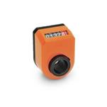
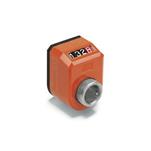
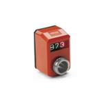
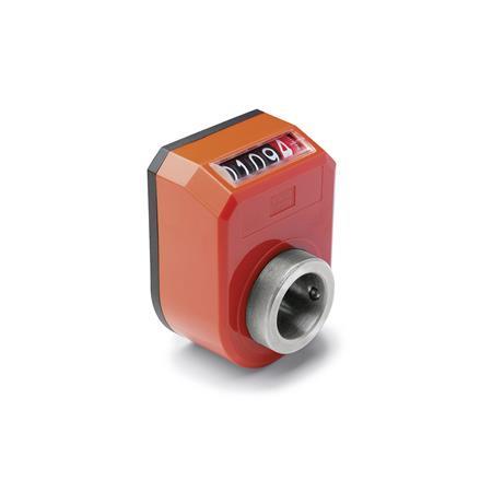
Position indicators GN 953.2 have a direct coupled drive with digital indication.
Both housing sections are ultrasonically welded, making the housing very tightly seated, stable and compact.
The foam rubber seal prevents the transmission of vibration to the counter and also acts as a seal.
The numbers are easily legible and they are even enlarged by the magnifying effect of the sight glass.
Housing
Plastic (Polyamide PA)


Numbers white,
number wheels for integers black,
for decimal numbers red
with additionally scale
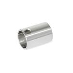
Hollow shaft
Stainless steel AISI 303
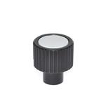
Grub screw DIN 916
with internal hexagon and serrated point
RoHS
Other counter display

| AN | On the chamfer, above |
| AR | On the chamfer, below |
| FN | In the front, above |
| FR | In the front, below |
| R | Numbers ascending clockwise |
| L | Numbers ascending anti-clockwise |
| Counter | Indication after one spindle revolution | Corresponds to thread pitch | Max. revolutions per minute |
|---|---|---|---|
| 000.50 | 50 | 0,5 | 500 |
| 001.00 | 100 | 1 | 250 |
| 0001.0 | 10 | 1 | 1500 |
| 0002.0 | 20 | 2 | 1250 |
| 0002.5 | 25 | 2,5 | 1000 |
| 0003.0 | 30 | 3 | 830 |
| 0004.0* | 40 | 4 | 625 |
| 0005.0 | 50 | 5 | 500 |
| 0006.0 | 60 | 6 | 415 |
| 0010.0 | 100 | 10 | 250 |

|
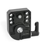
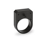
Before installation of the position indicator a bore for the torque limiting contact point is to be placed (see left). With the Adapter Bushings GN 952.1 the hollow shaft (with Bore 20 H7) of the position indicator can be adapted to fit the spindle. The mounting of the position indicator is via the torque limiting contact point which is connected to the hollow spindle and secured with a grub screw. With Clamping Plates GN 953.7 spindles can be clamped and secured after adjusting. |
||||||||||
|
The position indicator is equipped with a hollow shaft that is slid directly onto the spindle and is connected to the spindle by a grub screw. The spindle rotations are transmitted to a counter directly by a gearbox. For torque support, a pin of the housing projects into a hole made on the machine side, establishing the position relative to the mounting site. |
|||||||||||

|
The transmission ratio and counting direction of the counter are determined by the pitch of the adjusting spindle. The indicated value after one turn starting from the 0 position serves as a characteristic value. Decimal places are indicated in red. |
||||||||||
Our service team is available from Monday to Friday between 7:00 AM and 5:30 PM: +49 7723 6507 - 0