Our customers in the USA are managed by JW Winco. Please, use the website of JW Winco: jwwinco.com
Our customers in the USA are managed by JW Winco. Please, use the website of JW Winco: jwwinco.com
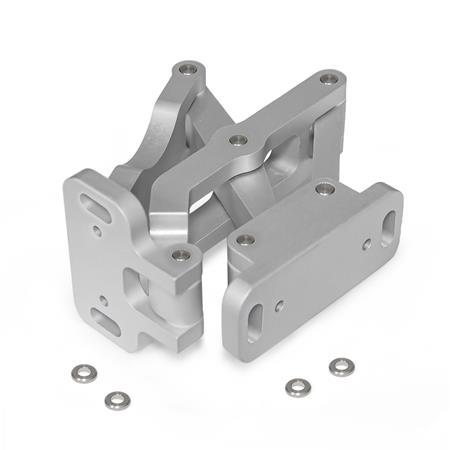
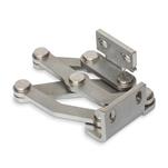
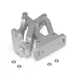
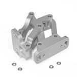
The multiple-joint hinge GN 7247 is installed on the inside of doors, flaps and hatches to save space and ensure protection against vandalism. The hinge has a maximum opening angle of 180°, which provides optimal accessibility and avoids the blocking of escape routes by open doors, for example.
Use of this hinge type leaves housing exteriors free of attachments that do not match the design or that should be avoided entirely in the interests of fast and easy cleaning.
Multiple-joint hinges are generally used in pairs. For higher loads, e.g. from large doors, these can be supplemented with additional hinges. Four reinforced washers are supplied, which can be used with fastening screws of thread size M6.
AluminumAL
Anodized, natural colorEL
Hinge pins / washers
Stainless steel 304
Friction bearing
Plastic
RoHS
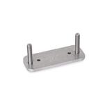
Spacer Plates GN 7247.2
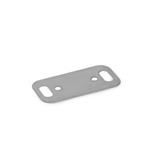
Plates GN 7247.4
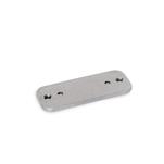
Plates GN 7247.6
Other finishes / colors
Other fastening flanges
Other opening angles
Other max. wall thicknesses
Other lifting motion

| l1 | d1 | d2 | h1 | h2 | l2 | l3 | l4 | l5 | l6 | l7 | l8 | l9 | l10 | m1 | m2 | m3 | m4 | m5 | r | s | x | y |
|---|---|---|---|---|---|---|---|---|---|---|---|---|---|---|---|---|---|---|---|---|---|---|
| 75 | 6,5 | 4 | 60 | 30 | 44,5 | 30 | 51 | 100,5 | 116,5 | 74,3 | 29,5 | 74 | 27 | 61 | 8 | 40 | 46 | 28 | 93 | 7 | 26 | 29 |
|
The multiple-joint hinges can be installed to the housing with the slots on the fastening flanges either parallel or perpendicular to the hinge axis. This results in the two pivot characteristics depicted. |
|||||||||||

|

|

|
The multiple-joint hinges can be adjusted in three planes during installation. For example, this allows adjustment for tolerances or establishing of required compressive forces for seals. Two planes can be adjusted via parallel or perpendicular slots in the fastening flanges. In the third plane, position corrections can be made using the spacer plates GN 7247.2. |
||||||||||
|
Doors, flaps and hatches can be inset, flush or mitered. The maximum wall thicknesses and bend sizes for sheet metal constructions given below arise from the respective installation type.
|
||||||||||||||||||||||||||||||||

|
||||||||||||||||||||||||||||||||
|
Show / Hide columns
|
||||||||||||||||||||||||||||||||
|
||||||||||||||||||||||||||||||||

|
||||||||||||||||||||||||||||||||
|
Show / Hide columns
|
||||||||||||||||||||||||||||||||
|
The design variants shown represent standard installation conditions. If the installation position of the hinge is changed or one of the two wall thickness dimensions is lower than s or b, the maximum achievable dimensions change independently of each other. This makes it possible in some cases to work with larger wall thickness dimensions than those specified with the same hinge size. A simple design check via CAD or a test setup is therefore recommended. |
||||||||||||||||||||||||||||||||

|
|
The maximum load of the multiple-joint hinge specified below applies to the standard use cases and serves for orientation in the case of deviating applications. The resulting forces lead to slight elastic deformation, which can be compensated for by means of the adjustment options, if necessary. |
||||||||||||||||||||

|
||||||||||||||||||||
|
Show / Hide columns
|
||||||||||||||||||||
Our service team is available from Monday to Friday between 7:00 AM and 5:30 PM: +49 7723 6507 - 0